


-
Water Cooling Central Air Conditioning
-
Screw/Centrifugal Air Compressor
-
Nano Ceramic Architecture Film
-
Company profile
-
Case
-
News
-
Contact us
Energy Plus Technology
Making the world greener, more natural
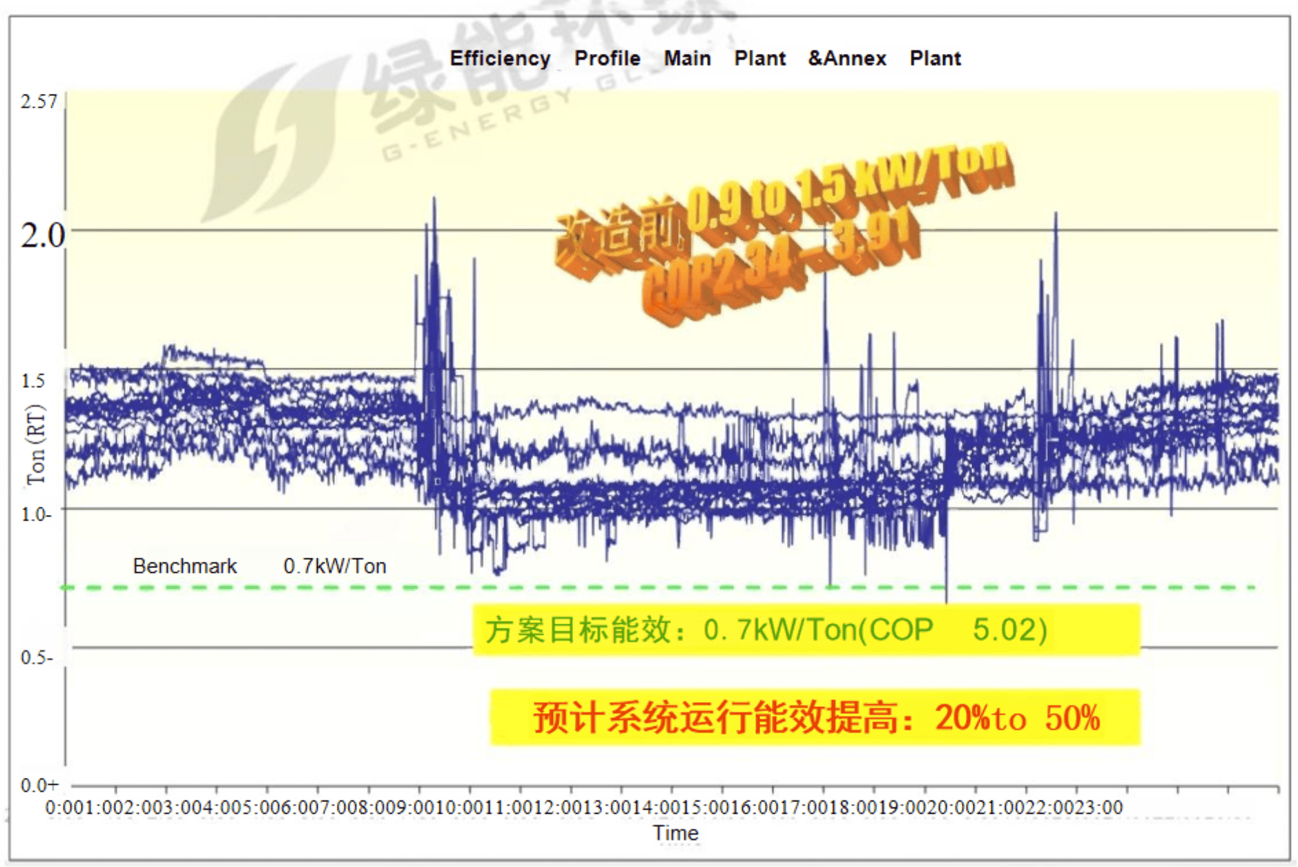
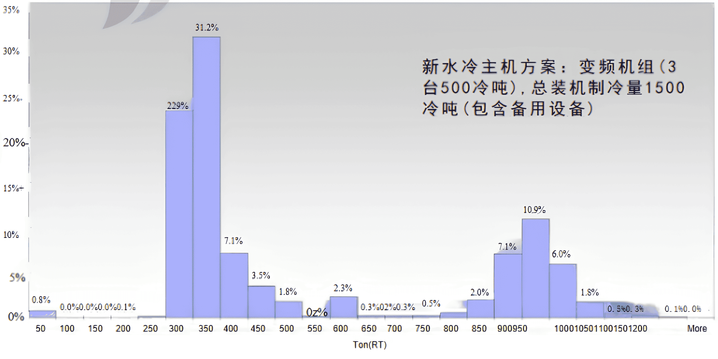
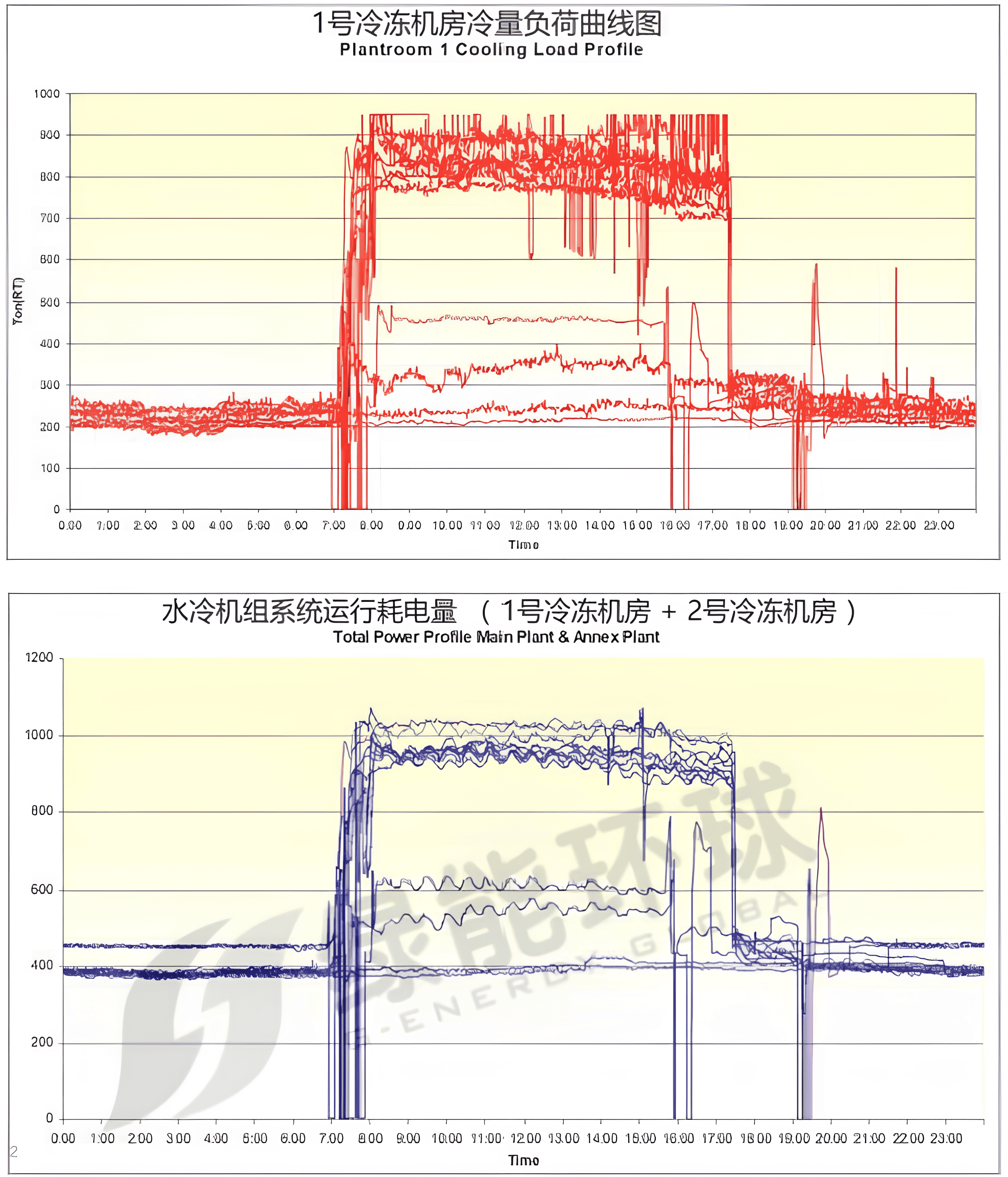
The reconstruction design scheme (determination of the host configuration capacity) is based on the analysis of the actual load proportion
Cooling capacity Operating proportion of load (No. 1 chiller plant room + No. 2 chiller plant room)
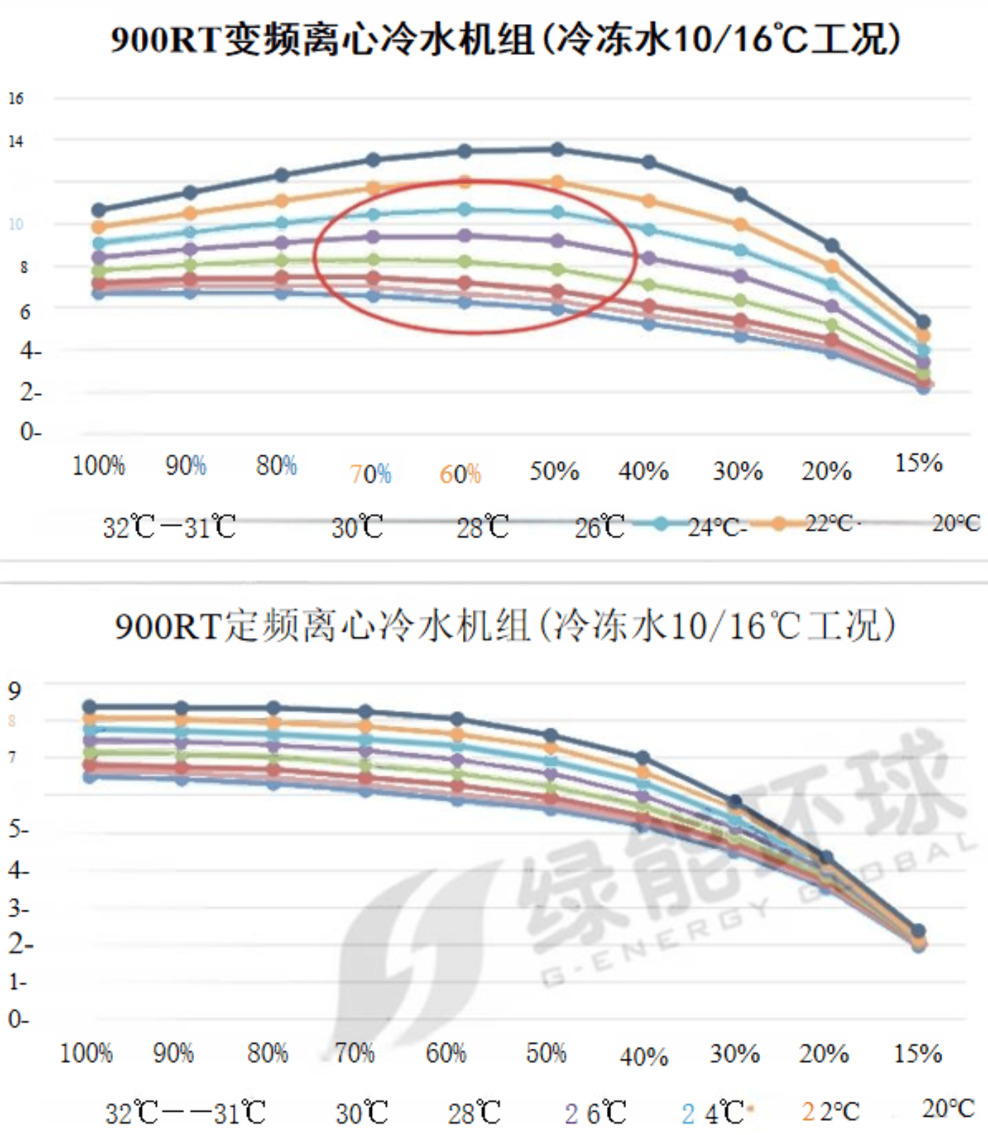
| 负荷率 load rate |
冷却水温度 Cooling water temperature | |||||||
| 32 | 31 | 30 | 28 | 26 | 24 | 22 | 20 | |
| 100% | 6.666 | 6.897 | 7.156 | 7.735 | 8.365 | 9.055 | 9.817 | 10.62 |
| 90% | 6.699 | 7.025 | 7.354 | 8.023 | 8.764 | 9.568 | 10.47 | 11.46 |
| 80% | 6.671 | 7.012 | 7.431 | 8.231 | 9.07 | 10.01 | 11.07 | 12.29 |
| 70% | 6.531 | 6.953 | 7.403 | 8.278 | 9.343 | 10.42 | 11.67 | 13.02 |
| 60% | 6.245 | 6.639 | 7.172 | 8.176 | 9.414 | 10.66 | 11.97 | 13.43 |
| 50% | 5.899 | 6.904 | 6.77 | 7.799 | 9.158 | 10.53 | 11.96 | 13.51 |
| 40% | 5.201 | 5.608 | 6.069 | 7.062 | 8.334 | 9.683 | 11.07 | 12.91 |
| 30% | 4.61 | 4.99 | 5.384 | 6.308 | 7.472 | 8.703 | 9.94 | 11.38 |
| 20% | 3.82 | 4.109 | 4.46 | 5.167 | 6.046 | 7.05 | 7.957 | 8.941 |
| 10% | 2.156 | 2.329 | 2.509 | 2.882 | 3.377 | 3.939 | 4.627 | 5.292 |
| 负荷率 load rate |
冷却水温度 Cooling water temperature | |||||||
| 32 | 31 | 30 | 28 | 26 | 24 | 22 | 20 | |
| 100% | 6.477 | 6.638 | 6.799 | 7.135 | 7.459 | 7.753 | 8.051 | 8.346 |
| 90% | 6.405 | 6.574 | 6.735 | 7.092 | 7.414 | 7.695 | 8.009 | 8.316 |
| 80% | 6.287 | 6.45 | 6.68 | 7.013 | 7.324 | 7.613 | 7.914 | 8.318 |
| 70% | 6.102 | 6.271 | 6.459 | 6.798 | 7.182 | 7.479 | 7.825 | 8.217 |
| 60% | 5.853 | 6.018 | 6.252 | 6.573 | 6.932 | 7.306 | 7.61 | 8.021 |
| 50% | 5.607 | 5.756 | 5.925 | 6.224 | 6.565 | 6.889 | 7.26 | 7.585 |
| 40% | 5.159 | 5.281 | 5.428 | 5.69 | 5.969 | 6.317 | 6.604 | 6.986 |
| 30% | 4.46 | 4.581 | 4.687 | 4.86 | 5.111 | 5.342 | 5.634 | 5.805 |
| 20% | 3.505 | 3.598 | 3.691 | 3.83 | 3.978 | 4.096 | 4.171 | 4.326 |
| 10% | 1.948 | 2.006 | 2.041 | 2.076 | 2.103 | 2.126 | 2.147 | 2.356 |
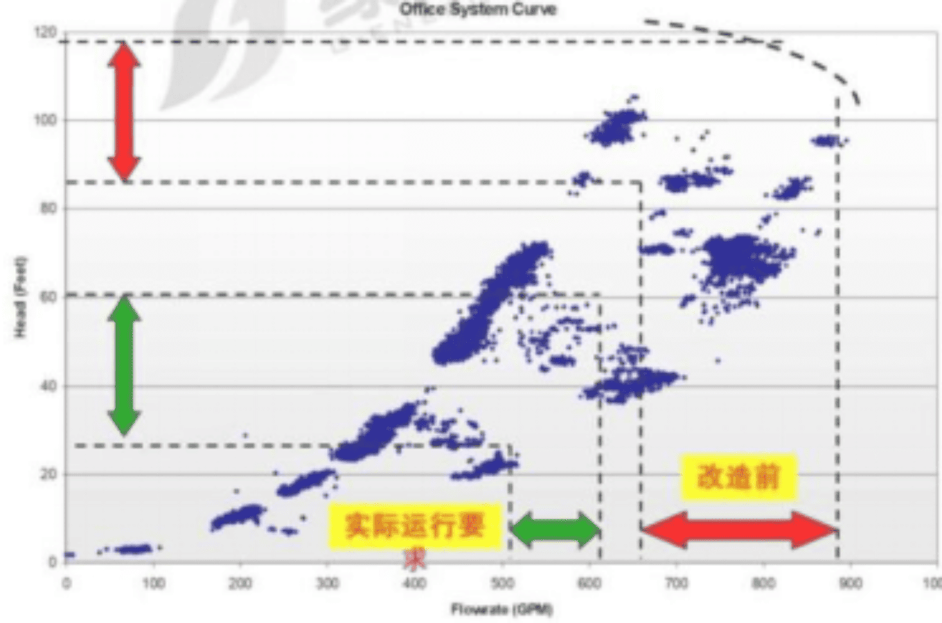
> Choose the tower with a stronger heat dissipation capacity if space allows.
> The selection increases the size of the tower body,reduces the wind speed on the windward side,and appropriately increases the heat transfer area of the packing.
> Pay attention to variable water characteristics: It is required that the water distribution should be even within the range of variable flow.
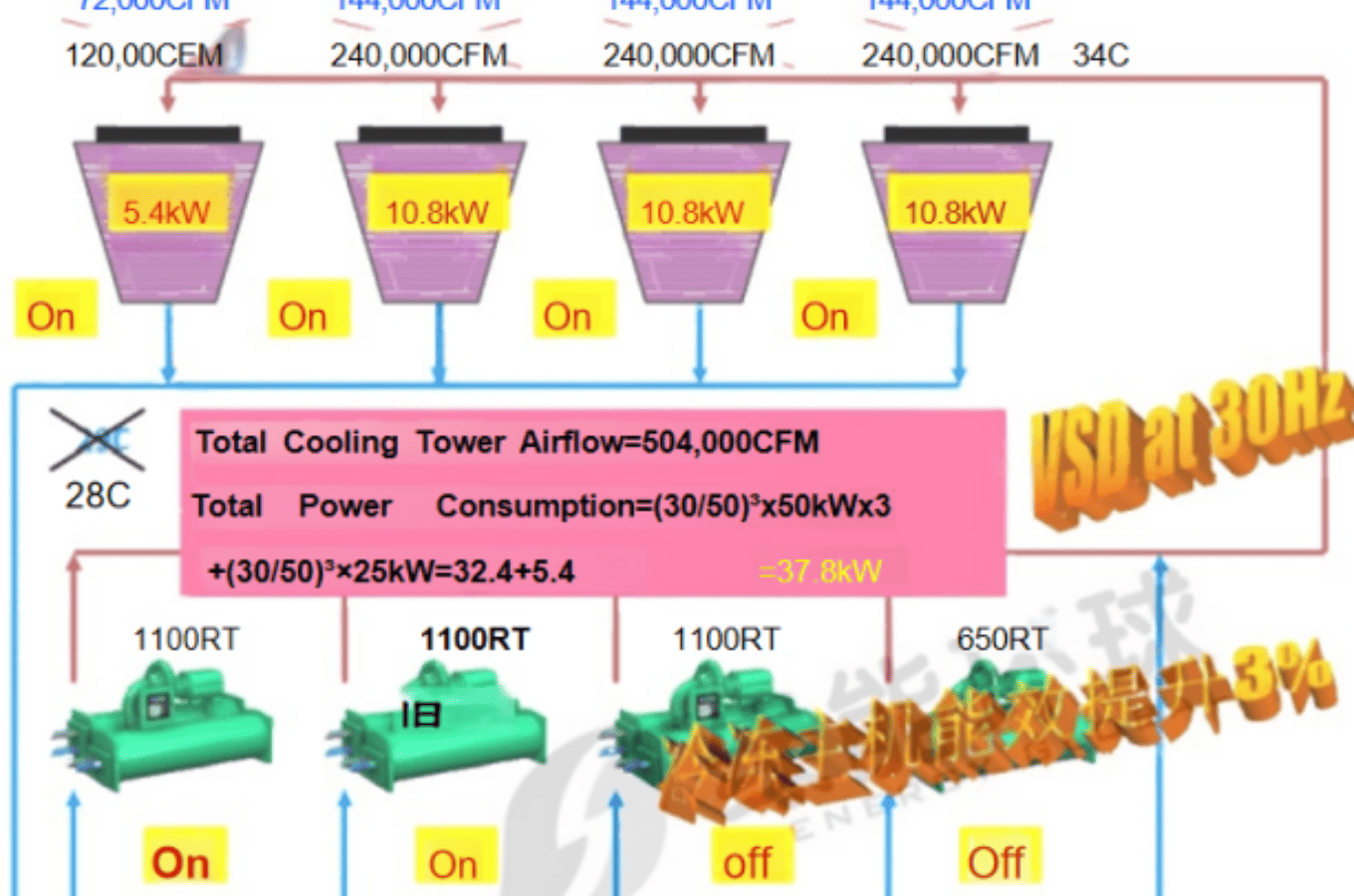
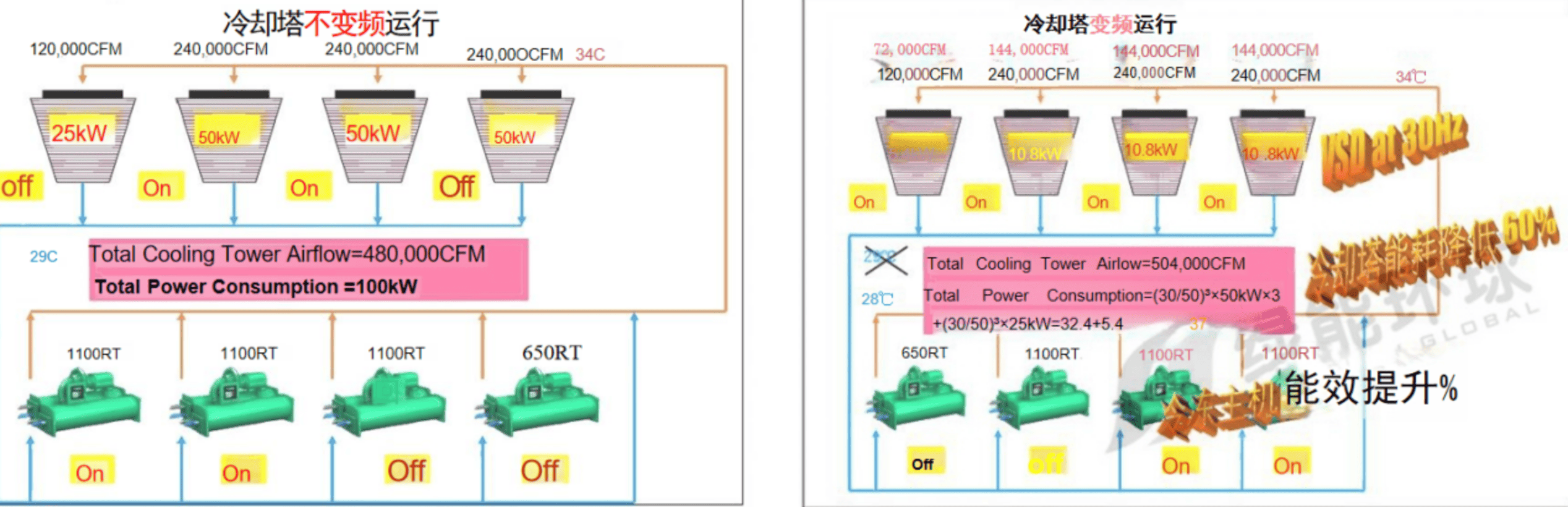
> Energy saving in actual operation: all fans of the cooling tower are controlled by frequency conversion, which is automatically realized by group control.
Seleciton parameter:31/36℃ or 30.5/35.5℃,Tws=28℃。
Seleciton parameter: 31/36℃ or 30.5/35.5℃,Tws=28℃。
Low resistance optimization of water system pipe network
Principle: The use of pipe network low resistance design, the use of low resistance pipelines and low resistance valves, reduce the pump head, reduce energy consumption:
■ Water pump inlet, low resistance Angle through automatic backwash filter instead of Y filter.
■ Water Pump outlet, low resistance eccentric spherical check valve, design flow launching resistance ≤5kpa.
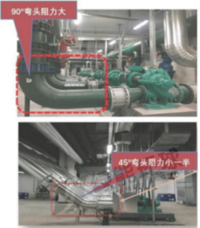
■ Low resistance pipe fittings: water tee, water elbow, 45° elbow instead of 90° elbow. See the figure below.
■ Cancel the water separator and collector.
■ Appropriately improve the pump foundation, and reasonably adjust the inlet and outlet pipe of the pump and the main engine to the inclined nozzle mode (or even the straight pipe mode) to reduce the resistance.
■ Precise hydraulic calculation of pipeline, precise selection of head.
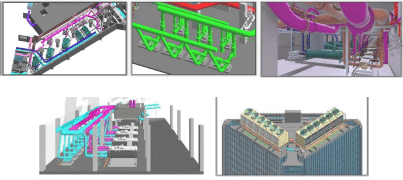
■ The main equipment room uses BIM drawing to guide on-site construction and reduce construction errors.
■ Technical control of the main equipment and accessories in the machine room.
■ To ensure the reliability of later operating data, the sensor installation position must be considered comprehensively.
> Use BIM drawing to reflect the actual pipeline and reduce the irrationality of pipeline crossing and routing in drawing
> Avoid the human error in the construction process, and realize the whole process supervision and control of energy saving project
· Intelligent group control system diagram, group control schematic diagram, point bitmap;
· Sensor installation diagram, system equipment list;
· Intelligent technical specifications, technical parameters of the hardware equipment of the group control system.
The efficient intelligent group control system is an intelligent system integration that monitors and controls the refrigeration host, cooling tower, freezing water pump, cooling water pump, electric valve and other mechanical and electrical equipment as well as the chilled water system and cooling water system in the entire refrigeration room system. It is a relatively independent subsystem at the BA management level.
· Automatic control, reduce human error;
· When the end load and outdoor weather conditions change, the system puts in the matching number of equipment and sets the appropriate operating parameters to make the system run efficiently;